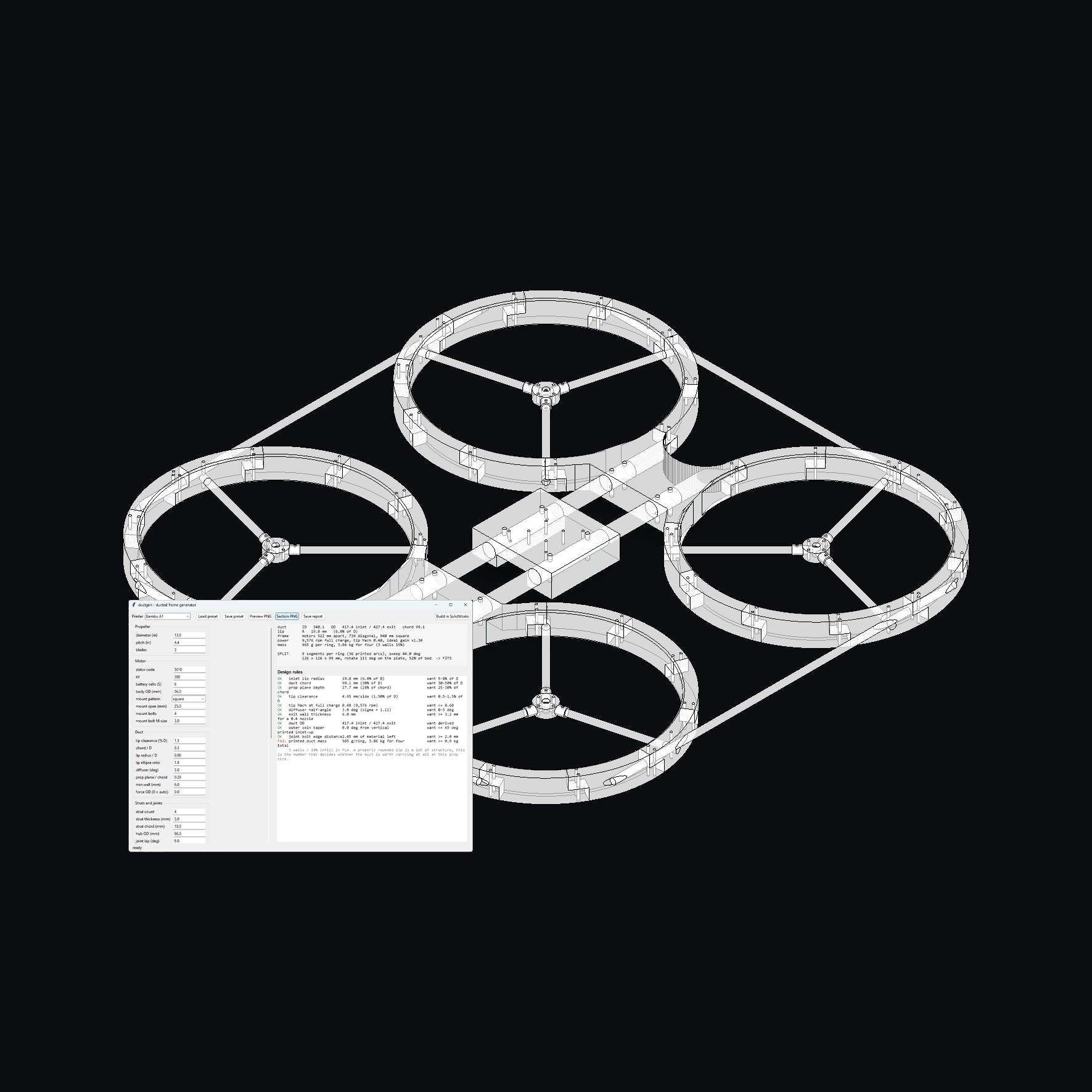
Ductgen is a parametric ducted quad frame generator that is designed to make the process of building a ducted quad alot easier. input prop size, motor, and the size of your printer bed, and it uses that information to figure out the duct section and how everything should be designed. Instead of having to manually work out all the measurements and sizes, it does that work then builds the parts.
build
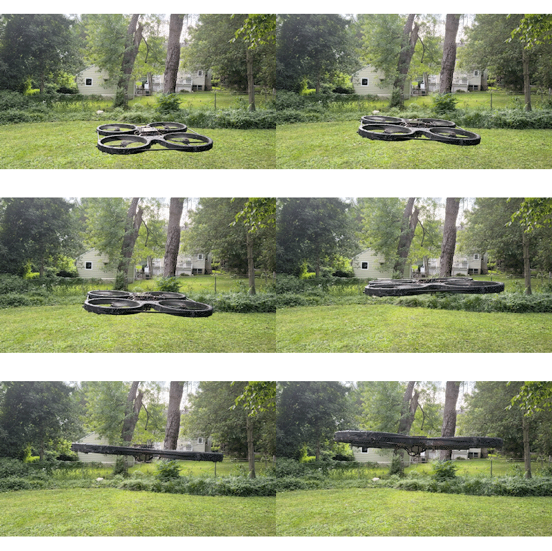
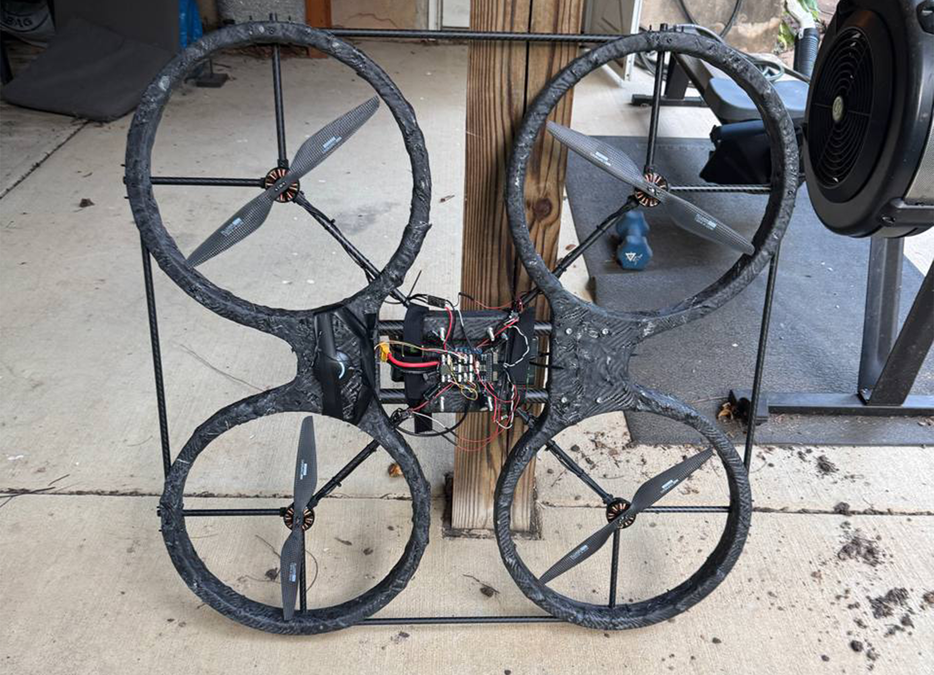
I made a 13in prop "ducted" quad that I
designed and printed myself: four 380 mm rings, 4006 380 kV motors on 6S,
three carbon arms per hub, half lap joints at mid height with two M3 each,
and a pair of 22.3 mm carbon tubes running the length of the fuselage as well as carbon fiber wrap/epoxy finish. Its not much of a "ducted" quad as much as it is a guard for the props, but it still does better for the thrust than an open air frame.
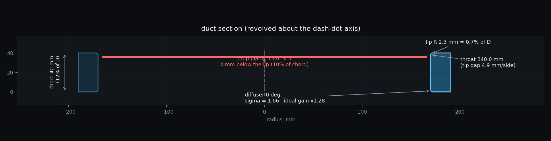
lip is a 2.3 mm radius on a 330 mm prop, which is 0.7 percent of diameter
flight was okay but it was seriously lacking on thrust. A ducted rotor only pays for itself if the
inlet stays attached, and static thrust guidance for a hover duct puts the
lip radius at 5 to 10 percent of prop diameter. Mine was 0.7 percent. The
chord was 40 mm, 12 percent of diameter against a usual 30 to 50. The prop
disc sat 4 mm below the lip, inside the lips own radius, so the blade tips
were working in the separated region instead of downstream of a reattached
one.
Three ratios, all wrong in the same direction, all compounding. this is definetely something I should have gone over before I printed the frame,
and it is the thing ductgen now does automatically.
dimensions
Before anything could be generated it had to be measured, so the reading
i made initially then the whole airframe was exported as a single mesh
and I had to take it apart in software.
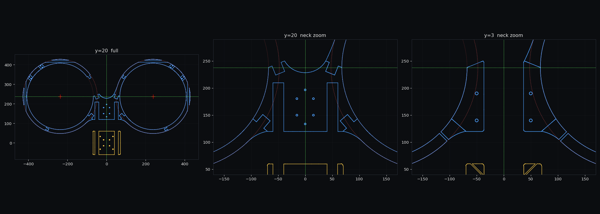
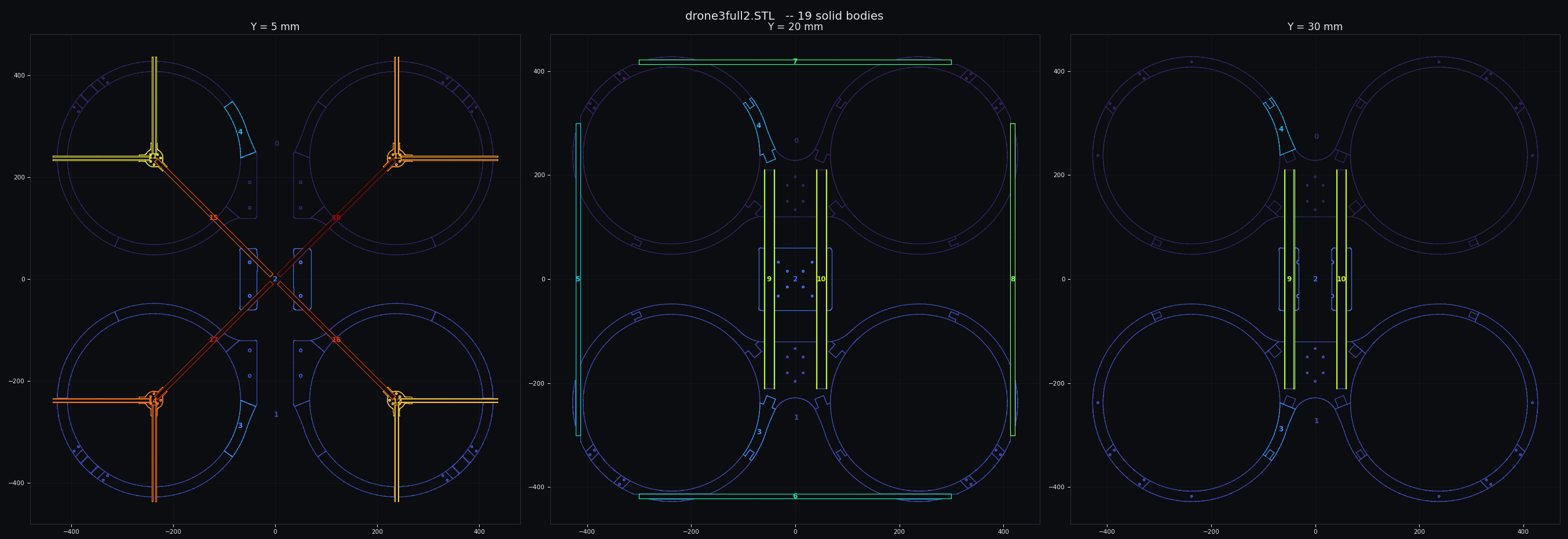
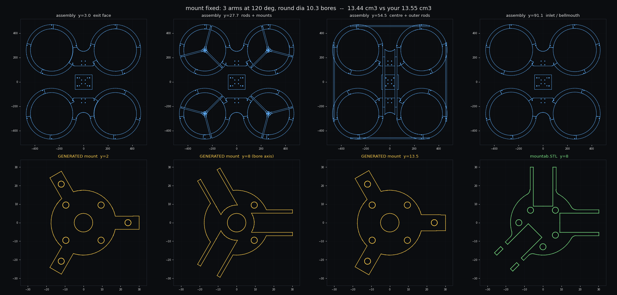
exported assembly split into labelled solid bodies and sliced at 3 heightsirl build 13" prop 380kv 4006 brushless motors, Pixhawk 2.4.8 FC, 9000mAh 6S, AM32 ESCs, Radiomaster RP1, PDB, external GPS. as well as (not shown) AI Stack Jetson orin nano, 4x OV9281 Camera
A STL reader gives bounding box, surface area and signed volume. A component splitter welds vertices onto a
tolerance grid then runs union find over shared vertices, which turned one
157,000 triangle file into 19 separate labelled bodies. A plane slicer
reports radius and angle clusters about any axis.
this way i was able to produce the references needed for the base generation: throat 340.0, OD 380.0, chord 40.0, motor
spacing 475.45, lip radius 2.3, a 30.5 mm flight controller pattern. Each
one is recorded with how it was made, because a few numbers could not
be measured at all. The prop plane depth is one of those.
geometry
The inputs reach the
geometry through the aerodynamics, and argues back when the
numbers do not add up.
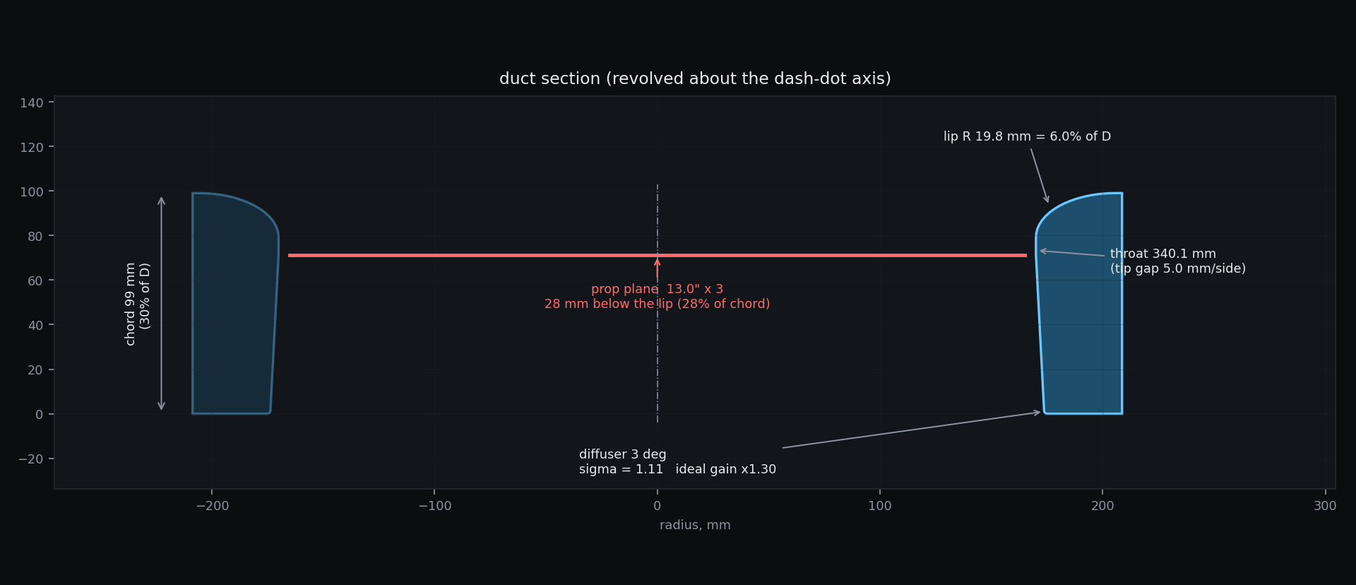
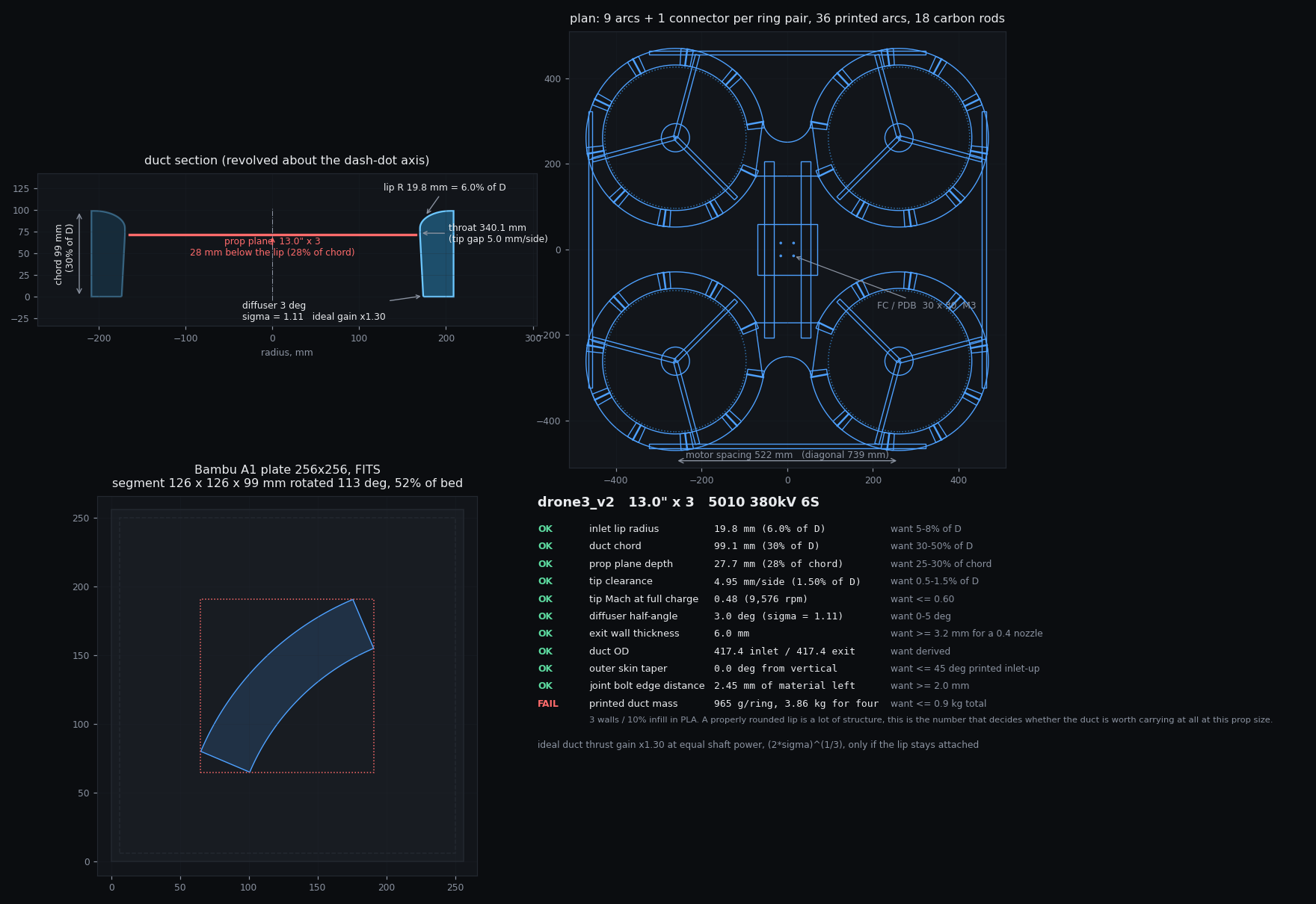
derived section at the same prop size. Lip radius 19.8 mm, 6.0 percent of diameter, on a 99 mm chord
prop diameter sets the duct ID at whatever tip clearance,
throat, chord, lip radius and prop plane depth scaled. kV x
cells gives rpm gives tip Mach, and it tells you when you cross 0.6.
Diffuser angle gives expansion ratio, which = the ideal static thrust
gain against an open rotor. Section plus printer to mass, per ring and
for four.
For example, a 6 percent bellmouth needs 36 mm of
radial room before there is any structure left, so asking for it inside a
20 mm wall makes the section self intersect. Instead of letting the revolve
fail, the duct OD grows to accommodate it and the report says the ring got
wider. Every rule prints their status with the number and the
target beside it.
The ring has to
become printable pieces, and where the cuts land matters structurally. By hand this is a lot of work. The ring is seperated into arcs and 2 middle connectors, and the arcs are phased to keep the joints off the strut roots.
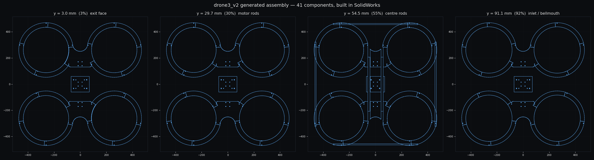
generated assembly sliced at exit face, motor rods, center rods, and the inlet bellmouth
the arc sector is tested at every in plane rotation, because a 256 mm bed
will swallow a much longer part across the diagonal. Joints are then phased
to keep them off the strut roots, so no glue line sits where the motor
loads are. All of the segments carry a half lap tab so consecutive
arcs overlap rather than butt together, and the connector between each duct
pair is cut as the exact complement of that lap, which closes the ring by
construction.
The carbon rods are the awkward part. A perimeter rod crosses the duct wall
as a chord, not a radial hole, and on this frame that chord across about
36 degrees of ring, roughly a whole segment. So it almost always continues
past a joint into the neighbour, and both parts need drilling. The first
version treated the bore as a point, gave the hole to the nearest segment
only, and left up to 60 mm of solid wall sitting exactly where the tube had
to pass.
Holes that sit at angles no reference plane can reach are handled by
rotating the solid body under a fixed plane, cutting, and rotating it back.
solidworks really would fight to not build a plane through the vertical axis, so the part
moves instead of the plane.
duct section, plan with cut lines and carbon cage + one segment on the bed
Prop
13 in, 3 blade
Motor
4006, 380 kV, 6S
Duct OD
380.0 mm as built / 417.4 mm derived
Throat
340.0 mm, 4.9 mm tip clearance per side
Chord
40.0 mm as built / 99.1 mm derived
Inlet lip radius
2.3 mm as built / 19.8 mm derived
Prop plane depth
10 percent of chord as built / 28 percent derived
Diffuser
0 deg as built / 3 deg derived, expansion ratio 1.11
Ideal thrust gain
x1.28 as built / x1.30 derived, at equal shaft power
Tip Mach
0.48 at 9,576 rpm full charge
Motor spacing
522 mm, 739 mm diagonal
Ring split
9 arcs plus 1 connector per ring pair, 126 x 126 mm each
Carbon
2 center tubes 22.3 mm, 4 cage rods 10 mm, 12 motor arms 10 mm
Hardware
80 M3 joint bolts, 16 M3 motor bolts
Printed mass
965 g per ring, 3.86 kg for four
Printer
Bambu A1, 256 mm bed, 52 percent plate utilisation