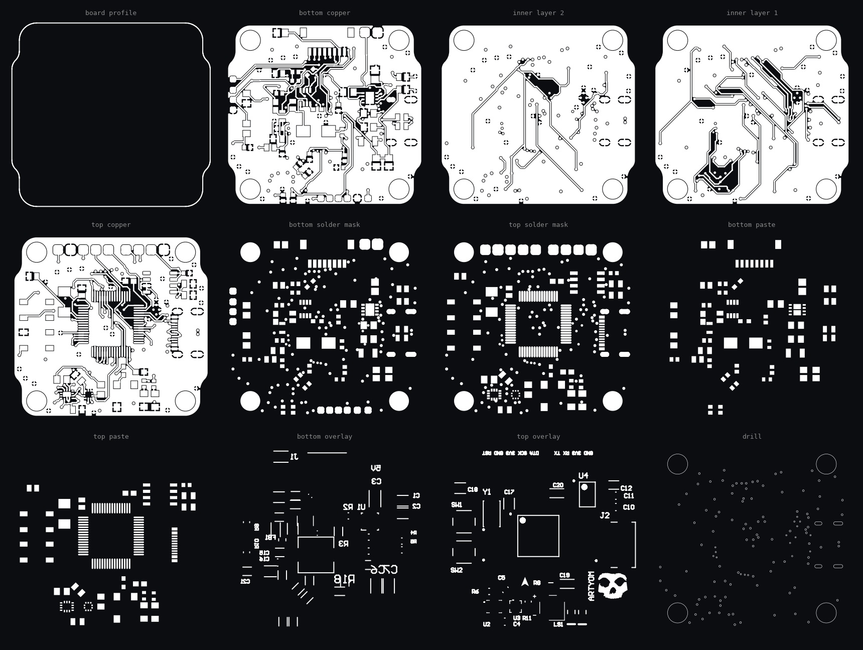



What the board is

STM32F405RGT6 mcu, a Cortex-M4 with a floating point unit, 168 MHz and a megabyte of flash in an LQFP64. Attitude comes from a BMI270 six axis IMU in a 2 by 2 mm LGA, altitude from a BMP384 barometer, and both sit on the same I2C bus as the MCU.
Power is the part that took the most board area. USB-C and the battery can both be plugged in at once, so a TPS2113A autoswitching mux decides which one feeds the board rather than leaving two supplies fighting over the same rail. This was the most difficult part to design. An MP2325 synchronous buck makes the 5 V rail at up to 3 A from the battery, through a flat wire high current inductor, and a TPS76633 LDO drops that to 3.3 V for the logic. A 1.1 A resettable PTC and a 600 Ohm ferrite bead sit on the input ahead of all of it.
Off the board there are four motor nets, an ESC input, telemetry, a current sense line, UART3, the I2C bus and SWD. Those leave through ten solder pads and an eight pin JST-SH side entry header. On top there is a 5 mm surface mount buzzer, two tact switches and two LEDs, and the edge pads are labelled in the overlay: DTA, SCK, 3V3, GND, RST for the debug row and TX, RX, 3V3, GND for the UART.
two builds: 1 carries the buck, and one drops U6, its inductor and its feedback divider for boards that are fed 5 V from somewhere else. in the one made i used the one without any buck converter, i made the mistake of shorting one of the pads on the inductor to the ground plane and it smoked the chip, so i had to order a new one. the one with the buck is more expensive, but it is more convenient to use.
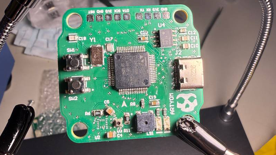
| Board | 40.0 x 37.0 mm, four copper layers |
|---|---|
| Mounting | 30 x 30 mm pattern, four 4 mm non plated holes |
| MCU | STM32F405RGT6, Cortex-M4F, 168 MHz, 1 MB flash, LQFP64 |
| IMU | BMI270, six axis, LGA-10 |
| Barometer | BMP384 |
| Input | USB-C and battery, switched by a TPS2113A power mux |
| 5 V rail | MP2325 synchronous buck, 3 A, 500 kHz, TSOT23-8 |
| 3.3 V rail | TPS76633 LDO, 250 mA |
| Protection | 1.1 A PTC, 600 Ω ferrite bead |
| Clock | 8 MHz, plus or minus 20 ppm |
| Connectors | 8 pin JST-SH side entry, 10 solder pads |
| Signals out | 4 motor nets, ESC in, telemetry, current sense, UART3, I2C, SWD |
| Also on board | 5 mm SMT buzzer, 2 tact switches, 2 LEDs |
| Holes | 125 total, smallest 0.2 mm |
| Placements | 56 parts across 36 BOM lines |
| Variants | with the onboard buck, and without it |
| Drawn in | Altium Designer 26.5.1 |